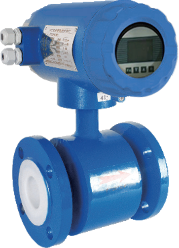
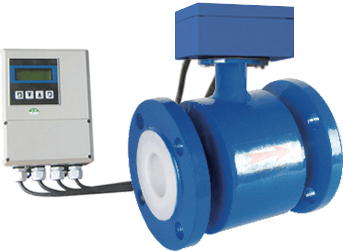
The electromagnetic flowmeter is less affected by the dispersion profile of the upstream flow velocity, resulting in relatively low requirements for devices such as the length of the front straight pipe. This is because in the early stages of electromagnetic flow meters in the 1950s and 1960s, smaller diameter flow sensors had longer measuring tubes, which had already played a role in adjusting the distortion activity to fully spaced. Therefore, there was no request for the length of the front straight pipe section in the early stages, and the accuracy of the appearance was relatively low, with fundamental errors ranging from ± (1.5~2.5)% Fs (full scale value). Even if there was activity distortion, it was only a fraction of the fundamental error, and the question was not prominent.
With the development of electromagnetic sewage flow meters, the diameter has increased from small to medium-sized to over 1m in domestic production, reaching 3m. With the planning and optimization of flow sensors, they are becoming increasingly lightweight and miniaturized. At that time, the length between the electromagnetic flow sensor and the pipeline connection surface was only 1.25 to 2.5 times the diameter (D), and the accuracy was improved everywhere, with a fundamental error of ± 0.5% R (measurement value). Therefore, everyone felt the need to set the length of the straight pipe section in a regular manner.
In 1991, the World Standardization Arrangement published IS09104 "Measurement of Liquid Flow in Closed Pipelines - Functional Identification Method for Liquid Electromagnetic Flowmeters", which stipulates that for flow calibration, the inner diameter of the connected flow meter pipeline shall not be less than the inner diameter of the flow sensor and shall not exceed 3% of the inner diameter of the sensor; The device is located in a straight pipe section at least 10D away from any upstream disturbance and 5D before any downstream disturbance at the sensor electrode axis base. When using the device, there are also requests from various external manufacturers that the distance between the device and the upstream disturbance component should be ≥ 5D.
In recent years, the use of standard meters for actual flow calibration has become popular, and many water flow calibration devices use high-precision electromagnetic flow meters as standard meters, with an accuracy level of usually 0.5 or as high as 0.2 to 0.3. The request for electromagnetic flowmeter devices used as standard meters is more stringent and cannot be treated as usual. Some instrument manufacturers install a straight pipe in front and behind the regular flow sensor with a precision of 0.3 level, and calibrate it after combining them. If it is disassembled and reassembled, it must be calibrated from the beginning.

For example, the experimental object is an electromagnetic sewage flow meter with a diameter of 50mm. Its inlet is connected to three sets of pipes, with inner diameters of 50mm, 55mm, and 45mm respectively. The inlet shoulder composed of 55mm and 45mm in between has exceeded the rules of ISO9104, and the receiving inner diameter difference is greater than or less than 10% of the inner diameter of the flow sensor. The flow sensor measuring tube is connected to the receiving end, and its base wire is concentric, straight, and horizontal from the pipeline base line, with a deviation of 3mm (6% of the outer inner diameter). Electromagnetic flow meters are modified by lengthening the measuring tube on a fixed surface, with two 30mm x 3mm observation windows opened horizontally and vertically at both ends of the measuring tube for measuring flow velocity dispersion using a laser Doppler velocimeter. The rubber fabric of the measuring tube is imported with a 7.5mm radius arc transition.

in summary
(1) The impact of migraine on traffic measurement values
The reception level bias disrupts the symmetry of the electrode base line due to the dispersion of flow velocity inside the measuring tube. If some conceal imports, causing the flow rate in the lower half to be relatively slower and some in the upper half to be relatively faster. If there is a slight pain due to straightness, some may conceal the right inlet to slow down the flow velocity on the right side and increase the flow velocity on the left side. From Figure 2, when the inner diameter of the receiver is connected to the flow sensor measuring tube, there is a positive change in error compared to concentricity, with a change of+(0.1-0.15)% for horizontal biases and a significant change of+(0.45-0.6)% for straight biases.
(2) The influence of interface shoulder on flow measurement values
When the inner diameter of the imported suction cup is smaller than the inner diameter of the flow sensor measuring tube, it becomes a sudden expansion tube. The liquid enters the measuring tube as shown in Figure 5 to form a stream, which is separated from some other media by the interface. It scatters and spirals into a fierce vortex, becoming a vortex vortex. As the vortex flows downstream, it gradually disappears and the flow beam extends to the entire cross-section. If the electrode orientation is within the vortex zone, it will affect the flow measurement value.
Copyright © Weibao Information Technology (Shanghai) Co,Ltd. All Rights Reserved